Intuitive 2nd Moment of Area
Update: You can watch a video version of this explanation, which takes a slightly different but more thorough approach, here.
The 2nd Moment of Area (2MA, or I) [\(m^4\)], which often goes by the term “Area Moment of Inertia”, is a concept that confused me for a long time. In first year engineering, I was taught to calculate this value by integrating over the cross-sectional area of an object according to the following equation (here, 2MA about the z-axis in the z-y plane):
\begin{equation} \tag{1} I_z = \int_{A} y^2 \,dA = \iint_{A} y^2 \,dzdy \end{equation}
In this formulation, the name “2nd Moment of Area” makes sense. It’s the amount of area, multiplied by that area’s distance from the axis (the moment) squared (hence the 2nd). But it doesn’t really give us an idea of what this value signifies, or how it’s useful to us. The units are certainly not of any help. m⁴? Is this some kind of 4-dimensional object?
The name “Area Moment of Inertia” gives some clues as to what this value really represents. Moment of Inertia implies a resistance to rotational motion, and Area implies that the cross-sectional area of an object is responsible for this resistance, not its mass. This is essentially what the 2MA is: it’s a measure of a shape’s ability to resist applied moments (torques), independent of the shape’s material. The 2MA tells us why I-beams are so effective at holding up ceilings, and why hollow tubes can be used to build a strong chassis.
But it’s still difficult to connect this idea of resistance to rotation with eq. (1) itself. To help us understand it conceptually, let’s explore the 2MA in the context of normal stress σx [\(N/m^2\)] due to a bending moment \(M_z\) [\(N \cdot m\)]in a beam, which is defined by the following equation, and illustrated in the diagram below:
\begin{equation} \tag{2} \sigma_x = -\frac{M_z \cdot y}{I_z} \end{equation}
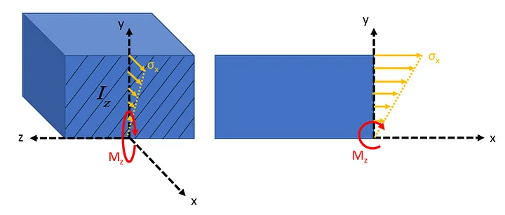
Eq. (2) shows that the further we go in the y-direction from the neutral (stress-free) x-z plane, the greater the stress. Moreover, the stress across the entire cross-section is divided by that cross-section’s 2MA (\(I_z\)). A larger \(I_z\) means lower stress σx. Since stress is what makes a material deform, this will result in less bending, or “rotation”. Hence, the 2MA resists rotation. But to get an understanding of the physical origins of 2MA, we need to take our example a step backwards to a much simpler system:
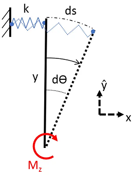
Here, we’re attempting to rotate an infinitely stiff bar connected to a spring with spring constant \(k\) [\(N/m\)] on the other end. For very small rotations, we can assume that the elongation of the spring is equal to the arc length ds [\(m\)]. In equilibrium, the restoring force of the spring must create an equal and opposite moment to counter \(M_z\) [\(N \cdot m\)], ie:
\begin{equation} \tag{3} M_{spring} = y \cdot F_{spring} = y \cdot k \cdot ds = M_z \end{equation}
From geometry, we know that
\begin{equation} \tag{4} ds = y \cdot d\theta \end{equation}
Substituting (4)->(3) and rearranging for the angle dθ,
\begin{equation} \tag{5} d\theta = \frac{M_z }{k \cdot y^2} \end{equation}
This shows us that the displacement angle is reduced by the square of the distance in \(y\) [\(m\)] from the neutral x-z plane. In other words, this distance \(y\) [\(m\)] works against the input moment \(M_z\) [\(N \cdot m\)] in 2 ways:
- It creates a larger moment arm for the spring force, and
- It increases the elongation of the spring, resulting in a larger spring force.
This combined effect is the meaning of the 2nd Moment, and is the origin of the \(y^2\) term from the integral in eq. (1). But what about the area? In real life, the “springs” that we’re dealing with are the bonds between atoms/molecules in a material. Because these bonds are so numerous, it makes sense to think of the “spring constant per unit area”, so to speak. We call this value the Young’s Modulus \(E\) [\(N/m^2\)], and we can equate the two by considering our earlier spring as a small cross-sectional area of material \(dA\) [\(m^2\)] in the y-z plane:
\begin{equation} \tag{6} k = \frac{E \cdot dA}{l_x} \end{equation}
Here, \(l_x\) [\(m\)] is the length of our material in the x-direction. Intuitively, a longer piece will elongate more (in absolute terms) than a shorter piece, since there is more material being stretched. Because the Young’s Modulus is a material constant that should be independent of geometry, it already normalizes for this length. To get our constant \(k\) [\(N/m\)], which is geometry dependent, we need to factor the length back in. Don’t get too held up on this though, because it’s going to cancel out very soon.
Let’s substitute (6)->(5):
\begin{equation} \tag{7} d\theta = \frac{M_z }{\frac{E \cdot dA}{l_x} \cdot y^2} \end{equation}
Now, let’s imagine that we want a way of comparing this system to another system with a different Young’s Modulus, or a different length, but the same cross-section. It would be convenient to group all the terms that result from the cross-sectional (y-z plane) geometry of our system. This is our infinitesimal 2MA:
\begin{equation} \tag{8} I_z = y^2 dA \end{equation}
Finally, let’s try to recreate equation (2) for our “area spring”. We’ll start with the force at equilibrium (with our small angle assumption, this force is in the x-direction):
\begin{equation} \tag{9} F_x = -k \cdot y \cdot d\theta \end{equation}
Notice how we have \(y\) as a multiplier on the force. This is because the further we get from our neutral y-z plane, the more our spring is stretched for a given angle of displacement. Now, we use (6),(7), and (8) to substitute in the values we want:
\begin{equation} \tag{10} F_x = -\frac{E \cdot dA}{l_x} \frac{M_z \cdot y}{\frac{E}{l_x} I_z} \end{equation}
And finally, since stress is simply the force per unit area, we divide out by \(dA\) [\(m^2\)] and simplify to obtain the same equation from (2):
\begin{equation} \tag{11} \sigma_x = -\frac{M_z \cdot y}{I_z} \end{equation}
It’s worth thinking about the fact that we’ve hidden a y² term in the 2MA, which one might simplify out of this equation. But keep in mind that in our simplified model, we considered only one spring. In a real beam, the 2MA is found by integrating across all the “springs” on the entire cross-sectional area. This resultant 2MA is global to the cross-section, and defines the angle of displacement for a given applied moment (depending also on the Young’s Modulus of the material). The \(y\) in eq. (11) is local, and defines the stress at a specific location on the cross-section for a given angle of displacement (the stress is material independent, since the Young’s Modulus cancels out in eq. (10)).
Let’s briefly review by considering how we obtain the [\(m^4\)] units of the 2MA:
- The Young’s Modulus relates to the spring constant per unit area, so to get the stiffness of our spring, we consider an infinitesimal area \(dA\). This gives us [\(m^2\)].
- The distance to the neutral plane acts as a moment/lever arm for our spring. The further this distance, the easier it is for our spring to act against moments. This gives us another [\(m\)].
- or every small angle of displacement, the distance to the neutral plane will act as a multiplier to the elongation of our spring, and hence its force. This gives us the final [\(m\)].
This is how I like to think about the 2nd Moment of Area, and if you’re struggling with it, I hope it helped you too!